Solar Street Light Wiring Guide: Avoid Mistakes & Ensure Safety
Nov 06, 2025
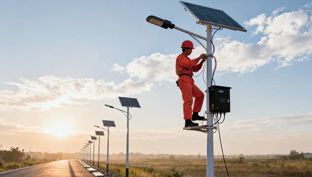
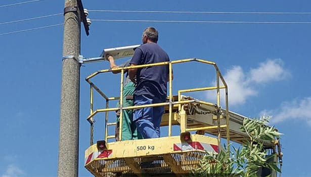
Solar street lights, with their advantages of being environmentally friendly, energy-saving and requiring no wiring, have become the mainstream choice for outdoor lighting. However, the wiring process is often overlooked. Industry data shows that improper wiring is the primary cause of early failure of solar street lights within three years, accounting for as high as 75%, and it is also the core trigger for safety accidents such as line overheating and fires. As industry warnings state: "Loose joints can generate local resistance, and long-term heating can easily cause the circuit to age and catch fire." The reverse polarity connection will instantly damage the controller and battery, directly leading to the scrapping of the equipment." NOKIN will comprehensively disassemble the core logic of solar LED street light wiring from the basics of wiring, technical key points, error avoidance to maintenance acceptance, helping construction workers, engineering contractors and operation and maintenance personnel accurately avoid pitfalls.
Solar Street Lights Wiring Range
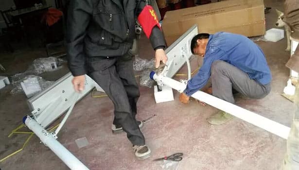
The wiring of solar powered street lights is not simply "connecting wires", but a systematic task covering the electrical connection of the entire system, involving the coordinated matching of multiple core components. Its associated components include: solar modules (PV panels), controllers (PWM/MPPT), batteries (lithium batteries/lead-acid batteries), LED light heads, junction boxes/waterproof connectors, grounding devices, combiner boxes and fuse protection components.
A complete wiring work not only requires the realization of circuit conduction between components, but also needs to take into account three core aspects: First, select the appropriate wire diameter based on the current and distance to avoid voltage loss; Second, ensure full-chain waterproof sealing to resist erosion from outdoor damp environments. Thirdly, it is necessary to achieve anti-loosening and anti-short circuit through standardized connection, and to be equipped with complete line protection measures. All three are indispensable.
Preparations before the Solar Street Lights Wiring Construction
Material Confirmation List
Before construction, the specifications of each material should be checked one by one to avoid rework or safety hazards caused by mismatched accessories.
|
Category |
Description |
|
Wire |
The DC cable selected according to the system power must clearly specify the wire diameter, material (copper core preferred), and weather resistance grade. |
|
Connectors and Terminals |
Use waterproof connectors matching the wire specifications (IP68 grade recommended), cold-pressed terminals, and terminal blocks. |
|
Protective Components |
Include fuses and circuit breakers suitable for the system’s operating current. |
|
Auxiliary Materials |
Use heat shrink tubing, waterproof glue, cable storage boxes, and cable ties. |
|
Tools |
Required tools include wire crimping pliers, wire strippers, a multimeter, a ground resistance tester, and insulating tape. |
Key Points of On-Site Confirmation
On-site conditions directly affect the wiring quality and system stability. Three core confirmations need to be completed before construction:
Foundation and light pole:
The light pole is firmly fixed, the reserved wiring hole position is reasonable, and there are no sharp edges to avoid scratching the cable.
Component layout:
The solar panels face south (in the Northern Hemisphere), free from trees and buildings to ensure sufficient sunlight.
Energy storage and grounding:
The location of the battery pit/outdoor electrical box is dry and well-ventilated. The grounding electrode has been installed in place, and the reserved length of the grounding lead wire is sufficient.
Solar Street Lights Wiring Key Technical Points
Cable and Cross-Sectional Area (Wire Diameter) Selection
Solar LED street lights are low-voltage DC systems. The selection of cable diameter directly affects voltage drop and line safety. If the wire diameter is too small, it will lead to increased loss when current passes through, not only reducing the power generation efficiency of the system, but also generating heat due to excessive resistance, causing cable aging and even fire. If the wire diameter is too large, it will increase the cost and construction difficulty.
The core principle for selection: Based on the maximum operating current in the circuit and the length of cable laying, choose the wire diameter in accordance with the recommended standards. The following is a recommended table of wire diameters for common solar powered street light systems (12V/24V):
|
System Voltage |
Maximum Operating Current (Example Load) |
Cable Length ≤10m – Recommended Wire Diameter |
Cable Length 10–20m – Recommended Wire Diameter |
Cable Length 20–30m – Recommended Wire Diameter |
|
12V |
5A (such as 10W light) |
1.5mm² |
2.5mm² |
4.0mm² |
|
12V |
10A (such as 20W light) |
2.5mm² |
4.0mm² |
6.0mm² |
|
24V |
5A (such as 20W light) |
1.0mm² |
1.5mm² |
2.5mm² |
|
24V |
10A (such as 40W light) |
1.5mm² |
2.5mm² |
4.0mm² |
Polarity and the Sequence of Connection Lines
Polarity error is the most fatal mistake in the wiring of solar street lights. Once the positive and negative poles are reversed, it will instantly burn out the controller, battery and even the LED light head. Moreover, such damage is usually not covered by the warranty.
Core wiring sequence
First, connect the battery to the controller:
The controller is designed with a battery priority connection protection mechanism. Connecting the battery first allows the controller to initialize and establish a basic voltage protection to prevent inrush current when other components are connected later.
Then connect the solar panels to the controller:
At this point, the controller is already in operation and can automatically detect the input voltage of the photovoltaic to prevent the high voltage generated by the photovoltaic panels from directly impacting the uninitialized equipment.
Finally, connect the load (LED light head) :
Make sure the controller has completed the adaptation of the photovoltaic to the battery before connecting the load to prevent the light from being burned out due to unstable voltage.
Tips:
When wiring, please note that the positive and negative pole markings of all components (" + "for positive and" - "for negative) must correspond exactly. It is recommended to use a multimeter to test the polarity of the components first before making the connection.
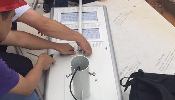
Joint, Waterproof and Anti-Loosening Treatment
In outdoor environments, the waterproof and anti-loosening performance of joints directly determines the lifespan of the system. Data shows that 60% of solar street light malfunctions are caused by poor contact due to water ingress or loosening at the joints.
Key points of standardized operation
Connector selection:
Prioritize the use of IP68 grade waterproof connectors to ensure no water ingress in harsh environments such as heavy rain and immersion.
Terminal treatment:
Use cold-pressed terminals to crimp cables. During crimping, ensure moderate force to avoid loose connections. After crimping, wrap with insulating tape.
Waterproof sealing:
Cover the cable joints with heat shrink tubes, heat and shrink them with a hot air gun, and apply waterproof glue to the interface gaps for double protection.
Anti-loosening measures:
After the joint is connected, it should be fixed to the light post or electrical box with cable ties to prevent the joint from loosening due to wind vibration and generating contact resistance.
Insurance, Fuses and Overcurrent Protection
Overcurrent protection is the "safety line" of solar street light wiring, which can effectively prevent equipment damage or fire caused by short circuits and overloads.
Core configuration requirements
Installation location:
The fuse/circuit breaker must be installed close to the positive output terminal of the battery to ensure that the power can be quickly cut off in case of a fault and protect the entire circuit.
Specification selection:
The rated current should be determined based on the maximum working current of the system, usually 1.25 to 1.5 times the maximum current. For example, for a system with a working current of 10A, a fuse with a rated current of 15A should be selected.
Maintenance convenience:
The installation location should be convenient for inspection and replacement, avoiding being hidden in confined Spaces. At the same time, proper markings should be made, indicating the specification parameters.
Grounding and Lightning Protection of Solar Street Lights
Outdoor solar street lights are vulnerable to lightning strikes and static electricity interference. Adequate grounding and lightning protection measures can safeguard the safety of the equipment and personnel.
Grounding system setup
Grounding electrode:
Galvanized grounding rods (length ≥2.5m) are used, which are vertically driven into the ground. The top of the grounding rod is ≥0.8m above the ground.
Grounding connection:
The solar panel support, light post, controller housing, and battery box all need to be connected to the grounding electrode through grounding wires. The diameter of the grounding wire should be ≥2.5mm².
Grounding resistance:
The grounding resistance value should be ≤4Ω. If the soil conductivity is low, the number of grounding electrodes can be increased or resistance-reducing agents can be laid.
Lightning protection ideas
External lightning protection:
Install a lightning rod at the top of the light pole to prevent direct lightning strikes on the solar panel or the light body.
Internal lightning protection:
Surge protectors (SPDS) are respectively installed at the photovoltaic input, battery input and load output terminals of the controller to absorb the instantaneous overvoltage generated by lightning strikes and protect electrical components.
Key Points for Wiring and Setting of Solar Street Light Controllers (MPPT/ PWM)
The controller is the "brain" of solar street lights, and its wiring standards and parameter Settings directly affect the operational efficiency of the system.
Terminal function identification
PV terminal:
Connects the positive and negative poles of the solar panel to receive photovoltaic power.
Battery terminal:
Connects the positive and negative terminals of the battery to achieve charging and discharging management.
Load terminal:
Connects the positive and negative terminals of the LED light head, controlling the on/off status and brightness of the light.
Core parameter Settings (On-site verification required)
Light sensing Settings:
Adjust the light control threshold according to actual needs. Generally, it is set to turn on the light when the light intensity is ≤10lux and turn off the light when it is ≥30lux.
Time control Settings:
Segmented lighting modes can be set (such as full lighting for the first 4 hours and half lighting for the last 8 hours) to match the lighting requirements at night.
Depth of discharge limit:
The recommended depth of discharge for lead-acid batteries is ≤50%, and for lithium batteries, it is ≤80%. This is to prevent over-discharge from damaging the battery.
Note:
The factory Settings of the controller need to be verified in combination with the on-site working conditions. For example, the duration of sunlight varies in different regions, so the charging protection parameters need to be adjusted.
Precautions for Battery Layout and Wiring
The wiring method and installation environment of a storage battery directly affect its service life and the balance of charging and discharging.
Wiring principle
Series/Parallel connection requirements:
When multiple batteries are connected in series or parallel, it is necessary to ensure that the battery models, capacities, and internal resistances are consistent to avoid the mixed use of new and old batteries.
Current sharing control:
When batteries are connected in parallel, the lengths of the connection cables should be kept consistent to reduce overcharging or overdischarging of individual batteries caused by uneven current distribution.
Connection sequence:
When multiple batteries are connected in series, first connect the positive and negative terminals between the batteries, and finally connect the main positive and negative terminals to the controller to avoid short circuits during wiring.
Installation environment requirements
Ventilation and heat dissipation:
Ventilation holes should be reserved in the battery box to prevent excessive temperature caused by a closed environment, which may affect battery performance.
Safety Protection:
Metal debris must not be placed in the battery box to prevent short circuits. The box body should be affixed with warning labels such as "High Voltage Hazard" and "No Open Flame".
Secure and stable fixation:
The battery should be fixed with a bracket or cable ties to prevent displacement and damage to the terminal blocks due to transportation or vibration.
Solar Street Lights Wiring Construction and Acceptance
|
Acceptance Project |
Acceptance Criteria |
|
Polarity Check |
All positive and negative terminals of the components are correctly connected, with no reverse connection. Confirm this through actual measurement with a multimeter. |
|
Cable Cross-Section Check |
Confirm that the cross-sectional area of the cable complies with the recommended standard. For long-distance use, ensure cables are not too thin.Check against the recommended wire diameter table. |
|
Waterproof Inspection |
The joint seal is intact, the heat shrink tube has properly shrunk, and there are no gaps. After rainy days, recheck to ensure no water ingress. |
|
Fuse Inspection |
The fuse is installed in the correct position, the rated current matches the system, and the marked specification parameters are clear for easy replacement. |
|
Grounding Test |
The grounding resistance value should be ≤4Ω, and the grounding connection must be firm. Test with a grounding resistance tester. |
|
Controller Setting |
The controller is configured with appropriate light control, time control, and discharge depth parameters, and should pass on-site simulation testing. |
|
Trial Operation |
Observe the system for 24–72 hours. Normal operation includes correct on/off timing and stable battery charging/discharging. Record charging voltage and lighting time. |
|
Label and Marking Check |
The battery box and controller terminals are clearly marked, and all warning labels are complete to ensure convenient future maintenance. |
Maintenance and Inspection of Solar Street Light Wiring
Regular maintenance of the wiring system of solar LED street lights can effectively reduce the failure rate and extend the service life of the equipment. It is recommended to follow the following maintenance cycles and priorities:
Quarterly Inspection
Pay special attention to checking whether the joints are loose and whether the waterproof seals are intact. If there is any aging, replace them in time.
Clean the dust and debris on the surface of the solar panels and check if the cables have any mechanical damage (such as squeezing or wear).
Semi-annual Inspection
Use a multimeter to measure the voltage of the battery and the open-circuit voltage of the solar panel to determine whether the charging and discharging are normal.
Check whether the fuses and surge protectors are in good condition and whether the grounding connection is firm.
Annual Inspection
Measure the grounding resistance value. If it exceeds the standard, timely rectification is required (such as adding grounding electrodes).
Check the controller parameter. Settings and adjust the time control mode according to seasonal changes (such as shortening the lighting duration in winter);
Conduct a comprehensive inspection of the aging condition of cables and replace any damaged ones in a timely manner.
FAQ
Q1: Why should the battery be connected first when wiring solar street lights?
A1: Connecting the battery first enables the controller to quickly initialize and activate the voltage protection mechanism. If the solar panels are connected first, the photovoltaic voltage may directly impact the unactivated controller, causing the internal components to burn out. Connecting the battery first can also prevent the surge current generated during subsequent wiring from damaging the equipment.
Q2: What should I do if the cable gets damp?
A2: Immediately cut off the power supply, remove the damp cable joint, dry the surface moisture of the cable with a dry cloth, and then dry the inside of the joint with a hot air gun. Check whether the insulation layer of the cable is damaged. If it is damaged, the cable needs to be replaced. When reconnecting, replace the new waterproof connector and properly seal the heat shrink tube and apply waterproof glue.
Q3: How can parallel batteries avoid uneven current?
A3: Ensure that the model, capacity and internal resistance of the parallel batteries are exactly the same to avoid mixing new and old batteries. The length and diameter of the connecting cables should be the same to reduce the difference in line resistance. When conditions permit, small balancing resistors should be connected in series in each battery branch to balance the charging and discharging currents.
Q4: What should I do if the solar street light doesn't light up after being wired?
A4: The first step is to use a multimeter to measure the voltage of the battery to determine if it is charged. The second step is to check whether the connection of the Load terminal of the controller is firm and whether the light control threshold setting is reasonable. The third step is to check whether the LED light head is damaged or if there is a short circuit or reverse polarity connection in the cable.
Q5: Do surge protectors (SPDS) need to be replaced regularly?
A5: Yes. After absorbing the energy of lightning strikes, the internal components of a surge protector will gradually age, and its typical service life is 3 to 5 years. It is recommended to check the status of the SPD annually. If the indicator window changes color (such as from green to red) or shows signs of burning, it should be replaced immediately.
The core of the wiring for solar street lights lies in doing well the three key points of "wire diameter matching, correct polarity, and waterproof and anti-loosening". This can not only prevent 80% of early failure problems, but also ensure the long-term safe and stable operation of the system. From the material verification before construction, to the technical specifications during construction, and then to the regular maintenance in the later stage, no link can be ignored.