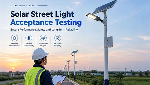
Solar Street Light Acceptance Testing: How to Measure Lux and Check Uniformity
Oct 26, 2026
At the delivery site of the solar street lighting project, a common dispute often occurs: the owner insists that the two lights are in a dark area and claims that the brightness does not meet the standards; the supplier presents the factory light flux report stating that the parameters are in line with the design indicators. Both sides hold different opinions and cannot provide reproducible measured data, thus the acceptance process gets stuck in an impasse.
The core contradiction of the negotiation is not the quality of the solar street lighting fixtures, but the failure to clearly define in the contract: what to measure, how to measure, and where to measure during the acceptance process. Visual inspection can only prove that the lights have been installed, but it cannot form a standardized conclusion; only by solidifying the illumination measurement (illuminance measurement), lux collection, and uniformity calculation into a feasible process can the subjective "is it bright or not" be transformed into objective data. This is precisely the starting point of solar street light acceptance testing.
Why Visual Inspection Is Not Enough for Solar Street Light Acceptance
Most disputes arise from relying on human eyes to determine the brightness, and human eyes have inherent defects in perception. Visual inspection can only prove that the solar street lights are installed properly, but it cannot determine whether the illumination meets the standards. This is also the reason why the standards do not recognize visual acceptance.
Human Vision Cannot Reliably Measure Illuminance
When the brightness doubles, the subjective perception only increases by approximately 30%; only when the measured value drops to 50% of the design value will people feel a significant dimming. This non-linear error directly causes differences in perception between both parties.
Ambient Light Can Affect Lux Readings
Evening residual sunlight, moonlight, shop lights, and passing vehicle lights will raise the road brightness. The real illumination is exposed only during the late night re-measurement.
Wet and Dry Road Surfaces Affect Lighting Perception
Dry asphalt absorbs light, while wet roads form mirror reflections. The illumination level measured by the same light can differ by more than twice; the readings taken in rainy and sunny conditions are not comparable.
Measurement Position Affects Perceived Brightness
Standing under the bright light of the light, walking to the middle of two solar street lights, a dark spot will immediately appear, and the local brightness cannot represent the overall level of the road.
The conclusion is clear: Visual inspection can only prove that the solar street lights are installed, but not that they meet the standards; smooth acceptance must abandon visual judgment and rely on standardized illumination measurement using an illuminance meter.
4 Conditions to Check Before Measuring Solar Street Light Illuminance
For the acceptance of street lights in the city, only environmental and equipment conditions need to be controlled. Solar street lights are also subject to battery power and dimming program constraints. The following 4 prerequisites are exclusive rules for solar street lights: any one of them not being met will invalidate all lux readings.
Confirm Battery Charge and Full-Power Operation
The output of the solar light strictly follows the battery SOC. When the battery is low, the controller automatically reduces power, and the measured illumination does not represent the product's capability. More importantly, lights with a time-based dimming profile usually operate at full power for the first 3 to 5 hours and then reduce power in the late night. Measuring during the dimming period will inevitably be不合格.
Operation standard: Confirm the dimming schedule in advance and lock the full power period; ensure sufficient charging the day before, confirm SOC at 100% before the test, and complete all measurement points collection in the full power and full output state.
Allow LED Output to Stabilize Before Measurement
There is a difference in light output between cold and hot states of LEDs. After 15 to 25 minutes of temperature rise balance, the light flux becomes stable; the maximum difference in lux between cold and hot states can reach 12%. Operationally, turn on the light and wait for 20 minutes, wait for the reading to be stable for 3 consecutive times before recording, and record the preheating duration in the acceptance record.
Control Ambient Light During Testing
The road illumination is formed by the addition of artificial lighting and environmental sunlight. Residual dusk light and full moon light will raise the reading, causing an overestimation. The measurement window should be selected in a completely dark period without strong moonlight, and record the start and end times and weather conditions; if there is strong natural ambient light, terminate the test and retest on another date.
Record the Cleaning Condition of the Fixture and Solar Panel
The dust on the light cover and mosquito stains directly reduce the light output; the dust on the panel affects the charging on the same day, indirectly causing a reduction in power at night. If not cleaned before measurement, the low illumination may be due to accumulated dirt rather than the performance of the solar street light. Whether the light and the panel are clean before measurement must be recorded, and if necessary, the comparison data before and after cleaning should be retained for future reference in case of disputes.
Self-check checklist: Full charge, full power, stable preheating, no environmental stray light, clean light and panel. All four items are indispensable; any one not meeting the requirements makes the measurement result invalid for acceptance.
How to Measure Solar Street Light Illuminance (Lux)
After the premise verification is completed, the actual measurement process begins. The entire illuminance measurement method (measurement method for illuminance) consists of four parts: selection, placement, height, and reading, ensuring the data can be reproduced.
Choose a Suitable Illuminance Meter
When answering "how to measure the lux of a street light", instrument selection is the first hurdle.
- Range: Match the on-site illuminance: main roads about 20 to 40 lux, secondary roads 10 to 20 lux, avoid high range with low precision to cause amplification errors.
- Cosine correction: Must have cosine correction (cosine correction), otherwise the reflected light will be missed, and the reading can be 20% or more lower.
- Calibration: The instrument must be within the calibration validity period, record the calibration certificate number and equipment number - this is the only valid evidence in case of disputes.
Set Up the Measurement Grid
According to the CIE 140:2019 "Road Lighting Calculations" (the second edition of CIE 140:2000): The measurement points should not only be placed directly below the light post, but also be placed longitudinally and laterally in the road section to form a rectangular grid, the spacing is determined by the installation height and accuracy requirements. The focus of single-light measurement is on the distribution curve and light spot shape, and for continuous road sections, the uniformity of the connection area between two lights is the focus; the measurement point coordinates are marked on the drawing, and the same set of points is used for re-measurement.
Position the Sensor at the Correct Measurement Plane
Road lighting takes the road surface as the measurement surface, the probe is placed horizontally and closely against the road surface for reading, not 1 meter below the light; the pedestrian area and special areas are determined by the corresponding standards for height. The measurement points must avoid the shadow caused by the measurement personnel themselves and obstacles such as utility poles, trees, and guardrails.
Record and Verify Illuminance Readings
Record the reading after the reading value at each point stabilizes, do not take instantaneous values; repeat reading at the same point, two sets of errors less than 5% can be adopted, abnormal points should be marked for on-site re-measurement. The fields of the record table include measurement point number, coordinates, reading, time, equipment number, weather, battery SOC; the original data is handwritten on-site and signed by both parties, and it is not allowed to fill in later.
How to Calculate Road Lighting Uniformity
Many solar street light lighting projects only assess the average illuminance Eavg, ignoring uniformity, and although the average is met, there are large areas of dark spots. Alternating light and dark switching will form a "zebra line effect", causing frequent visual adaptation by drivers, which is prone to fatigue and accidents.
Average and Minimum Illuminance
- U0: Total uniformity U0 = Minimum illuminance Emin ÷ Average illuminance Eavg, reflects the balance of light and darkness of the entire road surface; main roads usually U0 ≥ 0.35, rural branch roads not lower than 0.3.
- U1: Longitudinal uniformity U1 = Minimum illuminance Emin ÷ Maximum illuminance Emax, controls the light difference between adjacent solar street lights along the road direction, on main roads U1 generally not lower than 0.6.
Longitudinal Uniformity (Uₗ or U₁, Depending on the Standard)
The solar street light has inherent challenges in achieving uniformity: the single-point high-power solution often results in excessive brightness at the center and sudden drops at the edges, with the average illuminance barely meeting the standard while the Emin (minimum illuminance) is severely low, and the uniformity ratio (ratio of uniformity) fails to meet the requirements. The light distribution design is more important than simply increasing the wattage.
Identify Dark Spots Using Measurement Data
The determination method is to plot the grid measurement point data into an equal illuminance graph, and the dark areas can be visually identified. This entire set of street light uniformity calculation must be executed separately after the average illuminance verification is passed.
Why Measured Illuminance Differs from Design Values
"Why is my solar street light not bright enough" is the most frequent question at the site. When the actual measurement is lower than the design simulation value, the first action is not to rectify the light, but to follow the six-step path in Table to attribute and distinguish the responsibilities of the product, design, installation, and measurement, avoiding blind rework.
|
Cause |
Characteristics |
Verification and Validation Methods |
|
Luminous flux lower than nominal |
Overall illumination is lower at all measurement points, with a consistent proportional deviation. |
Verify the factory inspection report and re-measure the luminous flux through a third-party test. |
|
Height or elevation angle mismatch |
Range deviations occur, and the peak illuminance shifts away from the design point. |
Re-measure the pole height, overhang length, and light elevation angle on-site, then compare the results with the design drawings. |
|
Light cover contamination or light attenuation |
Light intensity gradually decreases over time. |
Measure and compare light output before and after cleaning, and assess the degree of LED light output degradation. |
|
Battery-related power reduction |
Readings vary significantly at different times during the same night. |
Repeat measurements with a fully charged battery, retrieve the controller logs, and verify the dimming settings. |
|
Measurement method error |
Data points are inconsistent, and the results cannot be reproduced. |
Re-establish the measurement points according to Section 3 and select an appropriate time window for re-measurement. |
|
Idealized light distribution curve |
Illuminance drops sharply at the edges of the illuminated area. |
Re-run the lighting simulation using measured light distribution data. |
Core conclusion: Six types of reasons correspond to six responsible parties and solutions. Without attributing the cause first, it is impossible to rectify; after identifying the responsible party, a solution can be determined, and the retest can be passed in one go.
What to Do If a Solar Street Light Fails Acceptance Testing
When the actual measurement does not meet the standard, the evidence sequence cannot be reversed; otherwise, the evidence will be invalid and there will be no basis for protecting rights.
Document On-Site Test Evidence
Capture panoramic shots, light position numbering, and on-site timestamp.
Record the calibration certificate number and equipment number of the illuminance meter.
Original reading table signed by both parties on-site, no backfilling allowed.
Sync record the battery SOC and controller status.
Both parties sign to confirm the measurement conditions.
Clarify Product, Design, and Installation Responsibilities
- Product responsibility: luminous flux mislabeling, rapid light attenuation, protective failure due to dust accumulation, controller failure causing power reduction.
- Design responsibility: incorrect light distribution selection, unreasonable pole height and spacing, illumination target deviating from the site.
- Installation responsibility: angle deviation, unaddressed obstructions, wiring problems causing power reduction.
Define the Re-Test Procedure
The re-test must be conducted under the same preconditions: fully charged, full power period, the same grid, the same calibrated instrument; results from inconsistent re-tests cannot be used as the basis for judgment.
Specify Acceptance Criteria in the Contract
Write the measurement method, measurement point diagram, measurement period, judgment criteria, calibration requirements into the contract attachment. Unclear acceptance terms are equivalent to no acceptance standards.
Sampling and Third-Party Verification for Batch Projects
Batch projects cannot be inspected in full for each light; they should be stratified sampled by batch and section, not just measuring the "most attractive light"; sampling must cover the ends of the section, bends, and obscured areas, etc., the most unfavorable points.
Suggested formal acceptance: Invite a CMA-qualified third-party institution to witness the sampling and issue a report, record the sampling rules, on-site conditions, equipment calibration, and both parties' on-site images. Measuring only the center point directly below the light pole and avoiding the dark spots of two lights is the most common fraud method, and third-party witness can effectively prevent it.
Solar Street Light Acceptance Testing Checklist
|
Phase |
Inspection Items |
Verification Requirements |
On-Site Record |
|
Prerequisites |
Full charge; operation at full power; LED preheating; no ambient light; clean measurement panel. |
All four prerequisite conditions must be satisfied; none may be omitted. |
Record the inspection time, power status, cleaning status, and weather conditions. |
|
Measurement |
Valid calibration certificate; measurement points based on the CIE 140 grid; probe in contact with the road surface; stable readings. |
Measurement points must correspond to the drawings, and the measuring instrument must be qualified. |
Record the equipment ID, calibration certificate number, and drawing number. |
|
Judgment |
Average illuminance (Eavg); minimum illuminance (Emin); overall uniformity (U0 = Emin/Eavg); longitudinal uniformity (U1 = Emin/Emax). |
All measured values and calculated uniformity ratios must meet the design requirements and applicable road lighting class specifications. |
Record illuminance readings and calculate both uniformity ratios (U0 and U1). |
|
Evidence Collection |
Timestamped photographs; signed original inspection form; controller logs. |
All evidence must be complete and unaltered. Both parties must be present to verify and confirm the records. |
Archive all evidence as the basis for acceptance and dispute resolution. |
Conclusion
The acceptance inspection of solar street lights is not just about "checking if they are on or not", but rather proving compliance through reproducible methods; solar street lights have an additional requirement - they must be measured during the fully charged and full power period. The average illuminance is only the basic threshold; the uniformity of U0 and U1 is the key to ensuring safe night driving; when there is a discrepancy between the actual measurement and the design, we will trace the problem step by step along the six-step path and assign responsibilities to the three parties. If you are also planning a solar street lighting project, please send us your project requirements. The professional solar street lighting team of NOKIN will match the pole height, light brightness and spacing of the solar street lights for you based on your road grade and climate environment, etc.